Abstract : In order to realize the automatic control of broadcasting and broadcasting tasks, a DX-200kW MW transmitter automation system with a programmable logic controller as the core is designed to realize the condition monitoring, intelligent scheduling and automatic control of the transmitter. Practice has proved that this automated system has a reasonable layout, simple and intuitive operation interface, good anti-interference, and can work stably in the transmitter room.
Key words: Transmitters; Smart dispatch; Condition monitoring; Automatic control Introduction In recent years, the Radio Station Administration of the Radio, Film, and Television Administration has actively promoted the construction of a modern central radio and television transmission coverage system based on its own safe transmission and transmission services, and standardized the safe transmission of transmission stations. Launch automatic control system, integrate various services of the Wireless Bureau, and optimize resource allocation considerations. As an important model broadcasted safely by the wireless bureau, the DX-type 200kW all-solid-state digital AM MW transmitter produced by Harris Broadcast Division has passed the application of a single-machine automation system, and the cycle time of the reliable receiver room operation monitoring system has been issued. The operation schedule, control the transmitter to complete the security broadcast task, real-time monitoring of various operating data, according to the operating status of the equipment, provide sound and interface alarms, summarize and manage the transmitter operating information, fault information, and operation log to achieve the launch pad The centralized control of the transmitter is integrated into the entire transmission transmission scheduling system of the wireless bureau.
1. The automation system structural design automation system consists of upper computer subsystem and lower computer subsystem. The host computer subsystem provides a good man-machine interface monitoring interface. The lower machine subsystem uses AB's programmable logic controller SLC500 series as the core control device to achieve data acquisition and device control. The upper computer and the lower computer realize data exchange through the DH+ protocol and adopt the design concept of “centralized management and decentralized controlâ€.
When the upper computer is abnormal, the lower computer can still operate independently; when the lower computer is abnormal, the upper computer provides the sound and light alarm in time. In order to improve reliability and security, the automation system is powered by an uninterruptible power supply (UPS) and uses a data server for data storage and backup. The structure of the automation system is shown in Figure 1.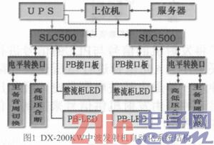
The upper computer subsystem is arranged in the control room of the engine room, which is convenient for users to monitor and control the transmitter status: the lower position subsystem is installed inside the transmitter, and the system accesses the transmitter interface circuit in a parallel manner, without changing the original circuit and ensuring the transmission is not affected. Machine original function. The operating functions on the transmitter's control panel and the automation system's operating functions are independent of each other. The control authority can be switched by turning the "remote/local" switch on the transmitter control panel. In the “remote control†state, the transmitter is controlled by the automation system. In the “local stateâ€, the automation system only has the function of monitoring the transmitter status and does not control the transmitter's function.
2. The related circuit design automation system uses programmable logic controller (PLC) data acquisition and reliable control to build a lower-level subsystem. The circuit design uses fieldbus technology, independent control, integrated wiring, and data sampling in a point-to-point manner. transmission. Automatic switch collection circuit shown in Figure 2, through the MC74HC152 three-eight wire 8 selection 1 multi-channel digital switch to switch state acquisition.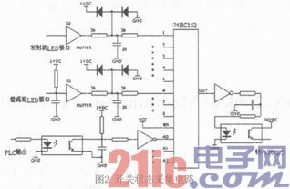
The analog data acquisition circuit of the automation system is shown in Fig. 3. The analog data is collected through the MAX378 three-eight wire eight-one-to-one multi-channel analog switch.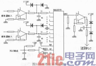
In order to match and isolate the transmitter signal from the PLC signal, the HI11A photocell is used for voltage conversion and isolation. The circuit is divided into two types, one is powered by a switching power supply and controlled after depressurization; the other is controlled by a transmitter for signals. Signal matching isolation circuit shown in Figure 4.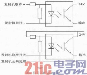
The switch sampling point and the input module of the PLC are optically isolated. Between the analog input and the input module of the PLC is a transmitter that can convert voltages with different levels and different differences into 0-5V standard voltage. After the processed sampling signal is sent to the PLC, the data is transmitted to the upper computer subsystem through a fast and stable field bus. In addition, in order to ensure that the manual operation and automatic operation function achieve the coordination work and do not affect each other, the power supply interlocking circuit design is adopted. When set to the manual operation mode, the automation system automatically disconnects the power of the automatic control circuit; when set to the automatic operation mode, the automation system automatically disconnects the manual control circuit power supply. In any case, you can directly operate the control panel to complete the transmitter control, high and low voltage power switch cabinet combination, disconnection, and program source and standby line switching and other operations, the local manual operation has the highest authority.
3. The main functions of the automation system function design automation system are as follows:
3.1 Manual/Automatic/Overhaul Switching Functions The automation system has three operating modes: manual, automatic and overhaul. Under manual control, the original manual operation function of the transmitter is preserved. Completely separated from the automation system is manually controlled; under automatic control, the transmitter is controlled and operated by the automation system; under the state of inspection, the automation system is completely controlled and manually controlled. The transmitter automation system mode adopts a hardware direct switching mode, and the switch is manually switched by the mode switch on the transmitter. In the manual mode, the automation system no longer automatically controls the monitoring and uploading of data according to the operation schedule with a periodical period; during the mode switching process, the security of the transmitter and the attached equipment is ensured; after the manual and automatic modes are switched, Keeping the original operating status of the transmitter unchanged; under the status of inspection, the automation system does not receive the operation schedule with cycle information and monitors but does not upload data; in the automatic mode, the transmitter automation system detects the execution date in the operation schedule as The current date, when the execution time does not end the task, it is executed immediately. The automatic working mode is the default working mode of the transmitter automation system. The transmitter automation system implements automatic control of the transmitter according to the periodic operation schedule, and monitors the operating status of the transmitter; when the transmitter fails, it is scheduled The settings for fault alarm, fault diagnosis and automatic switching.
3.2 Automatic Control Function When the automation system is in the “automatic†working mode, the automatic control function includes the operation schedule management, automatic switching of the transmitter, automatic disconnection of high and low voltage power supply, and automatic switching of the source and standby of the program source. Operation schedule management: The automation system exchanges data with the computer room operation monitoring system through Socket communication technology, and the operation schedule with cycle issued by the receiver room operation monitoring system. There are two types of operation schedule reception: manual intervention or automated system automatically completes the acceptance and confirmation of the operation schedule with period. In special cases, the operation and maintenance personnel can manually verify the operation schedule of the automated system with the cycle through identity verification; and can check the running time schedule of the current belt cycle at any time. Automatic switch machine: Automatic switch machine operation is completed according to the operation schedule with period. With advance test function, specific advance time is set on the computer, there are operating tips. Automatically cut off the high and low voltage power supply: According to the operating schedule with the cycle, the transmitter high and low voltage switch cabinets are automatically closed 3 minutes before the test machine; the transmitter working time period ends, the transmitter high voltage switch cabinet is automatically disconnected. Automatic switching of source and standby of program source: During the working period of the transmitter, the source of the main program is abnormal and it automatically switches to the source of the alternate program.
3.3 Real-time monitoring and fault alarm The automation system is in live working state to monitor the transmitter analog quantity, input switch quantity, output switch quantity, as well as the state of high and low voltage power supply switchgear and the status of main and standby lines of the program source. During the working period of the transmitter, the automatic system automatically resets and reboots when shutting down due to a fault. You can set the number of times that you need to turn on automatically through the human-machine interface. If you exceed the set number of times, you can provide sound and screen alarms manually.
3.4 Hours function The hour function is divided into automatic and manual hours. Automatic timing: The automation system uses the standard time issued by the Socket communication technology receiver room operation monitoring system to synchronize time and achieve automatic time calibration. Before the automatic calibration, if the difference between the automatic system time and the standard time exceeds a certain threshold value, the time synchronization is no longer required. At the same time, a warning prompt is issued to require manual intervention; Manual calibration: After the operation and maintenance personnel can pass the authentication, The automated system time is manually corrected.
3.5 Log Management Log management includes operation logs, table-value records, and fault and alarm records. Operation log: records the operation of all operation and maintenance personnel during the operation of the automation system. Table value record: Automatically record the monitored analog value every minute. If a fault occurs, the analog value of 60s before the failure is recorded. Fault and alarm records : Record the time and phenomenon of the automation system failure.
4. Man-Machine Interface Design Automation System Man-machine interface adopts multi-page display, simple and intuitive interface, user-friendly human-machine interface, real-time monitoring of the transmitter's various analog and digital data, fault information, operation log The operation and maintenance personnel can fully understand the operation of the transmitter. Automatic system prompt information is concise and accurate, easy to operate, realize the receiving of scheduling order, update and save the operation schedule, log query, time setting, working mode setting, and manual control of transmitter and other operations, all do not require operation and maintenance personnel to manually input information . The main interface of the man-machine interface of the automation system is shown in Fig. 5. The main interface mainly displays the broadcasting task of the transmitter, as well as the working status and operation data.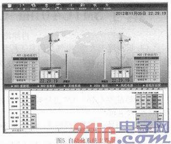
Displays the antenna number, transmitter operating status, operating mode, incident power, reflected power, amplifier voltage, amplifier current, network zero, antenna zero, amplitude, system time, PLC time, and currently being displayed in the most prominent position on the main interface. The executed color chart indicates the running schedule. The toolbar includes nine function navigation menus such as schedule management, broadcast management, query center, data processing, school hours, user management, system management, user registration and exit system. Click the corresponding function button to enter the next sub-menu, for example click on the transmitter to enter the transmitter switching and analog monitoring interface. When the 205V output, fan power supply, and high and low voltage switchgears are abnormal, they will flash red light with a buzzer alarm sound. Users can monitor key information such as system date, system time, working frequency, antenna, direction, program, incident power, reflected power and other transmitter operating status in real time at any interface. The status information column indicates the connection status of the automation system and the engine room operation monitoring system, the reception mode of the operation diagram, and the application method of the broadcasting application.
5. Conclusions The automation system took full advantage of the solid-state and digitalization of the DX-200kW medium-wave transmitter and provided various external interfaces for automatic monitoring. It was planned based on the principles of “simple, strict, practical, safe, and reasonable†and was designed. In applications, full consideration is given to the needs of safe transmission and transmission work, and the recommendations of the operation and maintenance personnel of the launching platform are widely adopted to strive for standardized design. The host computer interface is friendly, easy to operate, full-featured, and flexible in configuration. Lower computer wiring is simple, easy to install, easy to maintain, and stable operation. Since 2008, the DX-200kW medium-wave transmitter room has been widely used in wireless stations and has received good results.
Key words: Transmitters; Smart dispatch; Condition monitoring; Automatic control Introduction In recent years, the Radio Station Administration of the Radio, Film, and Television Administration has actively promoted the construction of a modern central radio and television transmission coverage system based on its own safe transmission and transmission services, and standardized the safe transmission of transmission stations. Launch automatic control system, integrate various services of the Wireless Bureau, and optimize resource allocation considerations. As an important model broadcasted safely by the wireless bureau, the DX-type 200kW all-solid-state digital AM MW transmitter produced by Harris Broadcast Division has passed the application of a single-machine automation system, and the cycle time of the reliable receiver room operation monitoring system has been issued. The operation schedule, control the transmitter to complete the security broadcast task, real-time monitoring of various operating data, according to the operating status of the equipment, provide sound and interface alarms, summarize and manage the transmitter operating information, fault information, and operation log to achieve the launch pad The centralized control of the transmitter is integrated into the entire transmission transmission scheduling system of the wireless bureau.
1. The automation system structural design automation system consists of upper computer subsystem and lower computer subsystem. The host computer subsystem provides a good man-machine interface monitoring interface. The lower machine subsystem uses AB's programmable logic controller SLC500 series as the core control device to achieve data acquisition and device control. The upper computer and the lower computer realize data exchange through the DH+ protocol and adopt the design concept of “centralized management and decentralized controlâ€.
When the upper computer is abnormal, the lower computer can still operate independently; when the lower computer is abnormal, the upper computer provides the sound and light alarm in time. In order to improve reliability and security, the automation system is powered by an uninterruptible power supply (UPS) and uses a data server for data storage and backup. The structure of the automation system is shown in Figure 1.

The upper computer subsystem is arranged in the control room of the engine room, which is convenient for users to monitor and control the transmitter status: the lower position subsystem is installed inside the transmitter, and the system accesses the transmitter interface circuit in a parallel manner, without changing the original circuit and ensuring the transmission is not affected. Machine original function. The operating functions on the transmitter's control panel and the automation system's operating functions are independent of each other. The control authority can be switched by turning the "remote/local" switch on the transmitter control panel. In the “remote control†state, the transmitter is controlled by the automation system. In the “local stateâ€, the automation system only has the function of monitoring the transmitter status and does not control the transmitter's function.
2. The related circuit design automation system uses programmable logic controller (PLC) data acquisition and reliable control to build a lower-level subsystem. The circuit design uses fieldbus technology, independent control, integrated wiring, and data sampling in a point-to-point manner. transmission. Automatic switch collection circuit shown in Figure 2, through the MC74HC152 three-eight wire 8 selection 1 multi-channel digital switch to switch state acquisition.

The analog data acquisition circuit of the automation system is shown in Fig. 3. The analog data is collected through the MAX378 three-eight wire eight-one-to-one multi-channel analog switch.

In order to match and isolate the transmitter signal from the PLC signal, the HI11A photocell is used for voltage conversion and isolation. The circuit is divided into two types, one is powered by a switching power supply and controlled after depressurization; the other is controlled by a transmitter for signals. Signal matching isolation circuit shown in Figure 4.

The switch sampling point and the input module of the PLC are optically isolated. Between the analog input and the input module of the PLC is a transmitter that can convert voltages with different levels and different differences into 0-5V standard voltage. After the processed sampling signal is sent to the PLC, the data is transmitted to the upper computer subsystem through a fast and stable field bus. In addition, in order to ensure that the manual operation and automatic operation function achieve the coordination work and do not affect each other, the power supply interlocking circuit design is adopted. When set to the manual operation mode, the automation system automatically disconnects the power of the automatic control circuit; when set to the automatic operation mode, the automation system automatically disconnects the manual control circuit power supply. In any case, you can directly operate the control panel to complete the transmitter control, high and low voltage power switch cabinet combination, disconnection, and program source and standby line switching and other operations, the local manual operation has the highest authority.
3. The main functions of the automation system function design automation system are as follows:
3.1 Manual/Automatic/Overhaul Switching Functions The automation system has three operating modes: manual, automatic and overhaul. Under manual control, the original manual operation function of the transmitter is preserved. Completely separated from the automation system is manually controlled; under automatic control, the transmitter is controlled and operated by the automation system; under the state of inspection, the automation system is completely controlled and manually controlled. The transmitter automation system mode adopts a hardware direct switching mode, and the switch is manually switched by the mode switch on the transmitter. In the manual mode, the automation system no longer automatically controls the monitoring and uploading of data according to the operation schedule with a periodical period; during the mode switching process, the security of the transmitter and the attached equipment is ensured; after the manual and automatic modes are switched, Keeping the original operating status of the transmitter unchanged; under the status of inspection, the automation system does not receive the operation schedule with cycle information and monitors but does not upload data; in the automatic mode, the transmitter automation system detects the execution date in the operation schedule as The current date, when the execution time does not end the task, it is executed immediately. The automatic working mode is the default working mode of the transmitter automation system. The transmitter automation system implements automatic control of the transmitter according to the periodic operation schedule, and monitors the operating status of the transmitter; when the transmitter fails, it is scheduled The settings for fault alarm, fault diagnosis and automatic switching.
3.2 Automatic Control Function When the automation system is in the “automatic†working mode, the automatic control function includes the operation schedule management, automatic switching of the transmitter, automatic disconnection of high and low voltage power supply, and automatic switching of the source and standby of the program source. Operation schedule management: The automation system exchanges data with the computer room operation monitoring system through Socket communication technology, and the operation schedule with cycle issued by the receiver room operation monitoring system. There are two types of operation schedule reception: manual intervention or automated system automatically completes the acceptance and confirmation of the operation schedule with period. In special cases, the operation and maintenance personnel can manually verify the operation schedule of the automated system with the cycle through identity verification; and can check the running time schedule of the current belt cycle at any time. Automatic switch machine: Automatic switch machine operation is completed according to the operation schedule with period. With advance test function, specific advance time is set on the computer, there are operating tips. Automatically cut off the high and low voltage power supply: According to the operating schedule with the cycle, the transmitter high and low voltage switch cabinets are automatically closed 3 minutes before the test machine; the transmitter working time period ends, the transmitter high voltage switch cabinet is automatically disconnected. Automatic switching of source and standby of program source: During the working period of the transmitter, the source of the main program is abnormal and it automatically switches to the source of the alternate program.
3.3 Real-time monitoring and fault alarm The automation system is in live working state to monitor the transmitter analog quantity, input switch quantity, output switch quantity, as well as the state of high and low voltage power supply switchgear and the status of main and standby lines of the program source. During the working period of the transmitter, the automatic system automatically resets and reboots when shutting down due to a fault. You can set the number of times that you need to turn on automatically through the human-machine interface. If you exceed the set number of times, you can provide sound and screen alarms manually.
3.4 Hours function The hour function is divided into automatic and manual hours. Automatic timing: The automation system uses the standard time issued by the Socket communication technology receiver room operation monitoring system to synchronize time and achieve automatic time calibration. Before the automatic calibration, if the difference between the automatic system time and the standard time exceeds a certain threshold value, the time synchronization is no longer required. At the same time, a warning prompt is issued to require manual intervention; Manual calibration: After the operation and maintenance personnel can pass the authentication, The automated system time is manually corrected.
3.5 Log Management Log management includes operation logs, table-value records, and fault and alarm records. Operation log: records the operation of all operation and maintenance personnel during the operation of the automation system. Table value record: Automatically record the monitored analog value every minute. If a fault occurs, the analog value of 60s before the failure is recorded. Fault and alarm records : Record the time and phenomenon of the automation system failure.
4. Man-Machine Interface Design Automation System Man-machine interface adopts multi-page display, simple and intuitive interface, user-friendly human-machine interface, real-time monitoring of the transmitter's various analog and digital data, fault information, operation log The operation and maintenance personnel can fully understand the operation of the transmitter. Automatic system prompt information is concise and accurate, easy to operate, realize the receiving of scheduling order, update and save the operation schedule, log query, time setting, working mode setting, and manual control of transmitter and other operations, all do not require operation and maintenance personnel to manually input information . The main interface of the man-machine interface of the automation system is shown in Fig. 5. The main interface mainly displays the broadcasting task of the transmitter, as well as the working status and operation data.

Displays the antenna number, transmitter operating status, operating mode, incident power, reflected power, amplifier voltage, amplifier current, network zero, antenna zero, amplitude, system time, PLC time, and currently being displayed in the most prominent position on the main interface. The executed color chart indicates the running schedule. The toolbar includes nine function navigation menus such as schedule management, broadcast management, query center, data processing, school hours, user management, system management, user registration and exit system. Click the corresponding function button to enter the next sub-menu, for example click on the transmitter to enter the transmitter switching and analog monitoring interface. When the 205V output, fan power supply, and high and low voltage switchgears are abnormal, they will flash red light with a buzzer alarm sound. Users can monitor key information such as system date, system time, working frequency, antenna, direction, program, incident power, reflected power and other transmitter operating status in real time at any interface. The status information column indicates the connection status of the automation system and the engine room operation monitoring system, the reception mode of the operation diagram, and the application method of the broadcasting application.
5. Conclusions The automation system took full advantage of the solid-state and digitalization of the DX-200kW medium-wave transmitter and provided various external interfaces for automatic monitoring. It was planned based on the principles of “simple, strict, practical, safe, and reasonable†and was designed. In applications, full consideration is given to the needs of safe transmission and transmission work, and the recommendations of the operation and maintenance personnel of the launching platform are widely adopted to strive for standardized design. The host computer interface is friendly, easy to operate, full-featured, and flexible in configuration. Lower computer wiring is simple, easy to install, easy to maintain, and stable operation. Since 2008, the DX-200kW medium-wave transmitter room has been widely used in wireless stations and has received good results.
Characteristics 1 Compact structure, easy operation and maintenance, and extended service life. 2 Reducers are driven by involute or double-arc herringbone wheels and thus can operate stably and reliably. 3 The entire machine is very light and thus can be installed and transported conveniently. 4 It is applicable in shallow oil production with small stroke and light loads.
Beam Balance Pumping Unit,Oilfield Pumping Unit,Oilfield Pumping Equipment,Wellhead Equipment Oilwell
Puyang Zhongshi Group Co.,Ltd , https://www.pycentralizer.com