Fresh fruit Juice making high capacity equipment disc centrifuge
Fresh fruit Juice making high capacity equipment disc centrifuge
Fresh fruit Juice making high capacity equipment disc centrifuge
Â
Specifications
Fuyi separator centrifuge were specially and professional designed for extremely demanding separation jobs. Key features of Fuyi separator centrifuge are its ability to handle high flow rates, high solid content and high-termperature process.
These functions make the centrifuge separator as the ideal choice to handle the tough conditions encountered in the animal and fish processing industries.
In addition , the fuyi centrifuge separator combines a high G-force from 6500 to 9800 , high sludge capabilities and automated operation. The centrifuge bowl can be made by Super Duplex stainless or normal Sus304, which makes it possible to combine extremely high erosion resistance with very high bowl speed for demanding separation duty.
Application
The Fuyi Centrifuge separator is designed for intermittent discharge of solids , while separating two intermixed and mutually insoluble liquid phases of different densities. In different optimized executions it is used for a large number of duties, from handing separation of fish press liquid , stick water and extract, and on the other hand purification of fish oil and liver oil , animal fats , peel oil and similar oil products.
Performance
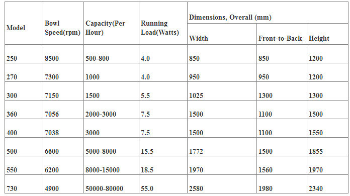
The actual throughputs depend on variables such as the amount and type of solid , the temperature , viscosity and degree of separation required. The following figures indicate the rate of performance, although no guarantees are given.
Fuyi Centrifuge Separator representatives or sale man will be please to provide you with further information and details.
Standard design
The machine consists of a frame that has a horizontal drive shaft with clutch and brake, worm gear , lubricating oil bath and vertical bowl spindle in the lower part.
The bowl is mounted on top of the spindle in the lower part. The bowl is mounted on top of the spindle , inside the space formed by the upper parts of the frame , the ring solid cover, the collecting cover, and frame hood . The feed and liquid discharge system , including the paring disc pump for the heavy phase, also rests on this structure. All parts in contact with the process liquid are made of stainless steel. The bowl is of the solid-ejecting disc type with hydraulic operating system. The electric motor is of the variable frequency drive type or of controlled-torque type.
Basic equipment
Concentrator or purifier parts, inlet and outlet devices, revolution counter, set of erosion-protective parts ,illuminated sight glass box for light phase outlet , vibration switch , vibration-isolating base plate , flange motor, set of tool and standard set of spare.
Optional extras
Started equipment, frequency converter, discharge control panel, standard set of fittings, set of CIP valves and fittings and serviceability package for online viewing of separator status
Material data
Bowl body , hood and locking ring S.S304
Solids cover and frame hood S.S
Frame bottom parts green cast iron , cald with
In and outlet parts S.S
Gasket and o-ring Nitrile rubber
Operating principles
Separation takes place inside a rotating bowl. The feed is introduced to the rotating centrifuge bowl from the top via a stationary inlet pipe (1),and is accelerated in the distributor(2),which was specially designed to ensure smooth acceleration of the feed liquid(4). Leaving the distributor, the feed enters the disc stack(3). The separation into liquid-liquid-solid takes place between the discs, with the oil phase moving through the disc stack to the centre. When it reaches the centre, it is discharged through hole (5) and ejected into the collecting frame. The water and heavy solid separated from the oil move to the periphery, and the water flows via channels in the top disc(6) to the paring chamber, where it is pumped out of the rotor by means of a built-in paring disc(7).During purification, hot water is fed into the inlet of the bowl before the process liquid is introduced. The water forms a seal around the outer edge of the top disc. The solid collect in the periphery where they are discharged intermittently via the centrifuge cyclone. The solid are discharged by means of a hydraulic system, which forces the sliding bowl bottom(8)to drop down at preset suitable intervals, thus opening the solid ports at the bowl periphery
Our company introduction:
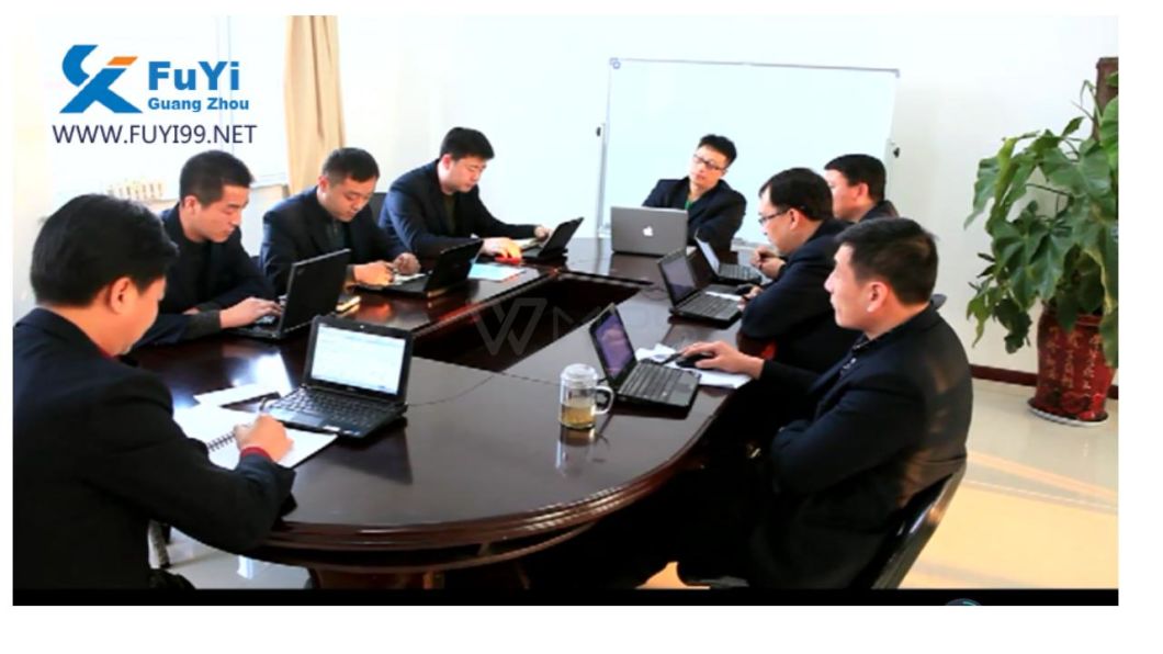
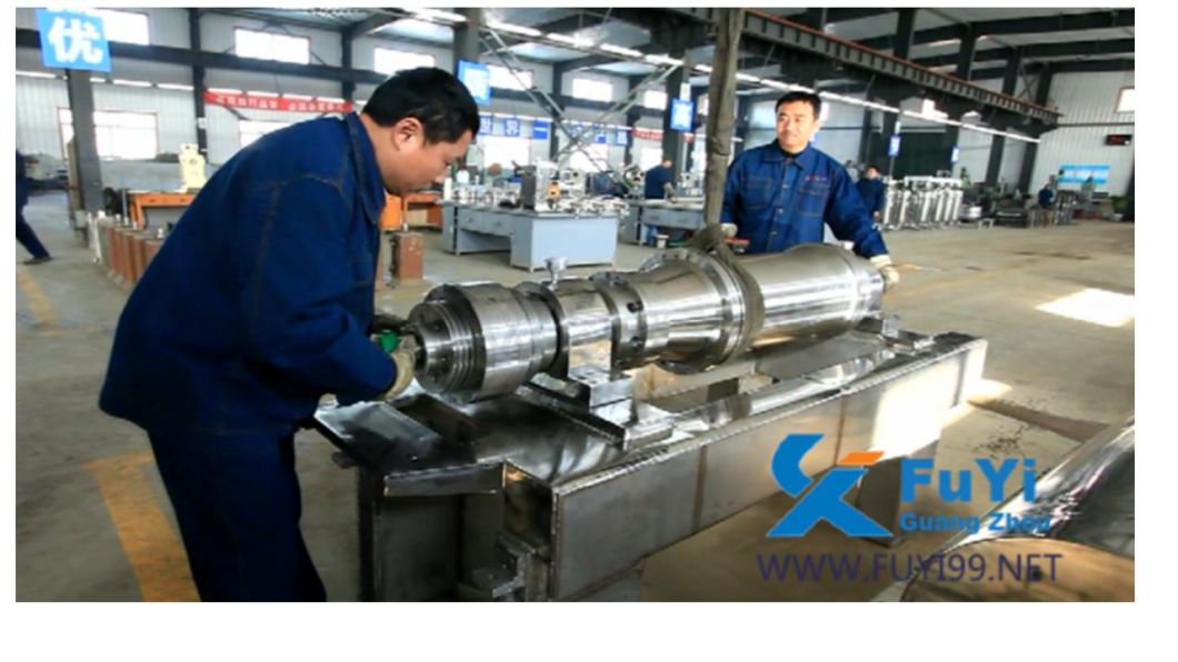
Our company was established in June 1986, formerly known as Guangzhou Fuyi Pharmaceutical Machinery Co., Ltd. Our company is now a technologically advanced and high-tech enterprise integrating R&D, production, and sales. Our company is a member of National separation machinery of Standardization Technical Committees, and also the Council Member of China General Machinery Industry Association. The director of our company is one of the first separation equipment researchers in China who obtained multiple National awards. "Tubular Separator", currently in effect, is the national standard and was drafted by our company. And in the same industry, our company is one of the first batches to pass ISO9001: 2000 quality system certification.
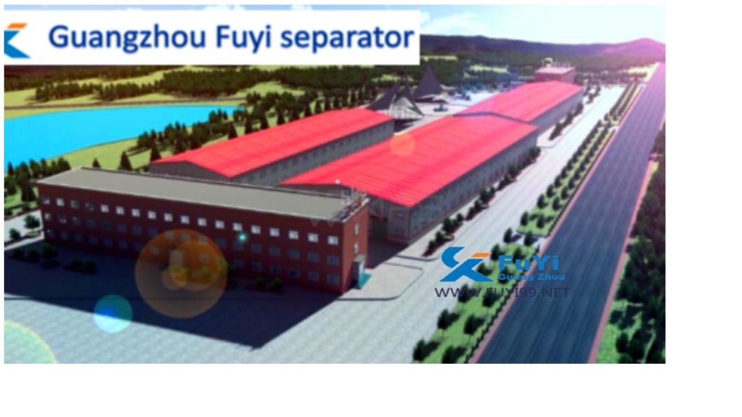
Our comprehensive performance has reached the advanced international level. Our company and branch office cover a total area of 60mu (1mu equals to 666.7m2) and a building area of 13, 000 square meters for equipment design and manufacturing, equipment inspection and test run.
With spare parts library and the material separation lab and the full equipped equipment, our company is one of the biggest manufacturers of separator equipment in domestic market. Our team is consisting of technology developers, PHD, postgraduates and undergraduates. We have close technical exchanges with Chinese Academy of Sciences, Zhejiang University and Tianjin University. We have won lots of national technical patents. Every year our company attends world-class meetings on separator machine and learns frontier technology.
Our equipment is widely used in pharmaceutical, chemical, food, beverage, blood products, material classification, biological diesel oil and other industries for the separation of solid and liquid or the separation of liquid and liquid. At present, there are thousands of equipment with all sizes have been used in lot of well known industries. As a domestic industry leader, we would like to provide our various products, excellence quality and perfect service to meet the market demand in the whole world, win the majority of users' trust and become the pioneer of the machinery manufacturing industry in the new century!
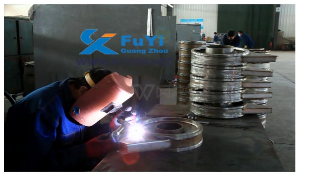
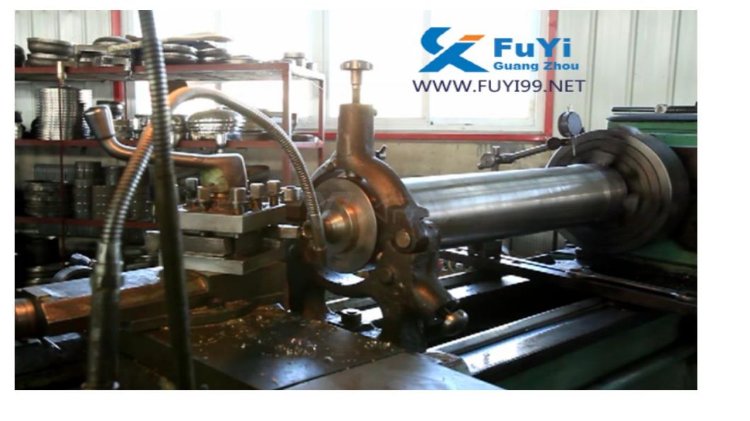
Â
The clamp with earth cable is used to make the electrical connection between the power source and the base material to be welded. The section and length of the cable are determined by the maximum current from the power source.
What does Grounding have to do with Arc Welding Safety
?
Grounding of electrical circuits is a safety practice that is documented in various codes and standards. A typical arc welding setup may consist of several electrical circuits. Applying and maintaining proper grounding methods within the welding area is important to promote electrical safety in the workplace. Associated processes such as plasma cutting will also benefit from proper grounding. The important grounding topics in a typical welding environment are discussed.
Grounding and Arc Welding Safety
Welding Machine Ground
Welding Machines that utilize a flexible cord and plug arrangement or those that are permanently wired into an electrical supply system contain a grounding conductor. The grounding conductor connects the metal enclosure of the welding machine to ground. If we could trace the grounding wire back through the electrical power distribution system we would find that it is connected to earth, and usually through a metal rod driven into the earth.
Grounding and Arc Welding Safety
The purpose of connecting the equipment enclosure to ground is to ensure that the metal enclosure of the welding machine and ground is at the same potential. When they are at the same potential, a person will not experience an electrical shock when touching the two points. Grounding the enclosure also limits the voltage on the enclosure in the event that insulation should fail within the equipment.
The current carrying capability of the grounding conductor is coordinated with the overcurrent device of the electrical supply system. The coordination of ampacity allows the grounding conductor to remain intact even if there is an electrical fault within the welding machine.
Some welding machines may have a double insulated design. In this case, a grounding conductor connection is not required. This type of welding machine relies on extra insulation to protect the user from shock. When double insulation is present it is identified by a "box within a box" symbol on the rating plate.
Grounding and Arc Welding Safety
For small welding machines that utilize a plug on the end of a power cord, the grounding conductor connection is made automatically when the welding machine is plugged into the receptacle. The grounding pin of the plug makes a connection within the receptacle. The use of adapters that effectively remove the grounding pin connection at the plug is not recommended. Furthermore, do not cut off or remove the grounding pin from the plug. All safety benefit of the grounding conductor is lost without the connection.
Grounding and Arc Welding Safety
Receptacle circuit testers will easily check the continuity of the grounding conductor. Receptacle circuit testers for 120-volt circuits are available at electrical supply or hardware stores; these inexpensive test devices plug into an electrical outlet. Indicator lights show whether the grounding circuit is available at the outlet, as well as other circuit tests. If the test device shows the absence of a ground connection or other circuit problem, call a qualified electrician for assistance. This is a simple test and should be done periodically. Consult with a qualified electrician to test circuits greater than 120 volts.
Grounding and Arc Welding Safety
Workpiece Ground
The welding circuit consists of all conductive material through which the welding current is intended to flow. Welding current flows through the welding machine terminals, welding cables, workpiece connection, gun, torch, Electrode Holder and workpiece. The welding circuit is not connected to ground within the welding machine, but is isolated from ground. How do we ground the welding circuit?
According to ANSI Z49.1, "Safety in Welding, Cutting and Allied Processes," the workpiece or the metal table that the workpiece rests upon must be grounded. We must connect the workpiece or work table to a suitable ground, such as a metal building frame. The ground connection should be independent or separate from the welding circuit connection.
Grounding and Arc Welding Safety
Grounding the workpiece has similar benefit to grounding the welding machine enclosure. When the workpiece is grounded, it is at the same potential as other grounded objects in the area. In the event of insulation failure in the arc welding machine or other equipment, the voltage between the workpiece and ground will be limited. Note that it is possible to have an ungrounded workpiece, but this requires the approval of a qualified person.
The Workpiece Connection is not a Ground Clamp
"Ground clamp" and "ground lead" are common terms used by many welders. The workpiece is connected to a welding cable typically by means of a spring loaded clamp or screw clamp. Unfortunately, a workpiece connection is often incorrectly called a "ground clamp" by many welders and the workpiece lead is incorrectly called "ground lead." The welding cable does not bring a ground connection to the workpiece. The ground connection is separate from the workpiece connection.
High Frequency Ground
Some welding machines utilize starting and stabilizing circuits that contain a high frequency voltage. This is common on Tungsten Inert Gas (TIG) welding machines. The high frequency voltage may have frequency components that extend into the megahertz region. In contrast, the welding voltage may be as low as 60 Hertz.
High frequency signals have a tendency to radiate away from the welding area. These signals may cause interference with nearby radio and television reception or other electrical equipment. One method to minimize the radiation of high frequency signals is to ground the welding circuit. The welding machine instruction manual will have specific instructions on how to ground the welding circuit and components in the surrounding area to minimize the radiation effect.
Portable and Vehicle Mounted Welding Generator Grounding
Portable and vehicle mounted arc welding generators often have the capability to supply 120 and 240 volt auxiliary power. These generators are used in remote locations away from an electrical power distribution system. A convenient earth ground is not usually available for connection. Should the generator frame be grounded?
The rules for grounding depend on the specific use and design of the auxiliary power generator. Most applications fall into one of the two categories summarized below:
1. If all of these requirements are met, then it is not required to ground the generator frame:
The generator is mounted to truck or trailer
The auxiliary power is taken from receptacles on the generator using a cord and plug arrangement
The receptacles have a grounding pin
The frame of the generator is bonded, or electrically connected, to the truck or trailer frame
2. If either of these conditions are met, then the generator frame must be grounded:
The generator is connected to a premises wiring system. For example, to supply power to a house during a blackout.
The auxiliary power is hard wired into the generator without the use of cords and plugs.
The summary above does not go into details and the reader is urged to consult their local electrical codes and ANSI/NFPA 70, "National Electrical Code" for the specifics.
Extension Cord Grounds
Extension cords should be periodically tested for ground continuity. Extension cords lead a rough life while lying on the ground; they are under foot and prone to damage. The use of a receptacle circuit tester will confirm that all of the connections are intact within the cord, plug and receptacle.
Welding Circuit Shock Hazards
Utilizing proper grounding in the welding environment is a good practice, but it does not remove all possibility of electrical shock. The welding circuit is energized by welding voltage. A person will receive a shock if they become the electrical path across the welding circuit. Precautions must be taken to insulate the welder from the welding circuit. Use dry insulating gloves and other insulating means. Also maintain insulation on weld cables, electrode holders, guns and torches to provide protection.
Similarly, electric shock originating from the electrical supply system can be prevented. Proper maintenance of electrical equipment and extension cords will insulate the welder from electrical sources.
Information Sources
American Welding Society, ANSI Z49.1:2005 "Safety in Welding, Cutting, and Allied Processes."

National Fire Protection Association, NFPA 70, "National Electrical Code", 2005.

American Welding Society, Safety and Health Fact Sheet No. 29, "Grounding of Portable and Vehicle Mounted Welding Generators", July 2004.

American Welding Society, AWS A3.0-2001, "Standard Welding Terms and Definitions."
Earth Clamp,Copper Earth Clamp,Copper Grounding Clamp,Brass Clamp For Earth
Changzhou Edaweld Trading Company Limited , http://www.edaweld.com