Keywords: telescopic level gauge, differential pressure transmitter, sensing tube 1 magnetostrictive level gauge composition and principles 1.1 composition magnetostrictive level gauge is a continuous level, interface measurement, and Provides a high-precision measurement instrument for monitoring and controlling the output of analog signals and consists of three parts: (A) magnetic float within 360 degrees; (B) sensors (piezomagnetic sensors and magnetic sensing tubes); (C) Plastic intelligent electronic device. Intelligent programming, with LCD display, can display the overall level, interface level, and the temperature output of the electrical signal, the actual level value, temperature, the actual level with the offset value.
1.2 Working principle A magnetostrictive line is installed in a non-magnetic sensor tube. A magnetostrictive sensor is installed at one end of the magnetostrictive line. The piezoelectric sensor emits 10 current pulse signals to the magnetostrictive line every second. In time, the current pulse interacts with the magnetic field of the magnetic float to generate a torsional stress wave on the magnetostrictive line that propagates along the magnetostrictive line from both ends of the float at known speeds. Until the piezomagnetic sensor receives this torsional stress signal, the piezomagnetic sensor can measure the time interval between the start pulse and the return torsion stress wave, and judge the position of the float according to the time interval, because the float is always suspended on the liquid surface. The position of the magnetic float changes with the change of the liquid surface, that is, the time interval is the level of the liquid level, and then the full-intelligent electronic device converts the time interval size signal to a 4-20 mA signal proportional to the measured liquid level ( HART) output.
2 Features 2.1 Advantages (1) The structure is simple and consists of only three parts;
(2) High precision, 0.01% of full scale, maximum error no more than 1.27mm;
(3) calibration is extremely simple, no real standard, just press the button or use the HART protocol;
(4) No need to re-calibrate for recalibrating or forgetting the calibration value;
(5) Large measuring range, 0~22m;
(6) Simultaneous measurement of total fluid level and interface fluid level, as well as temperature output;
(7) Large pressure range, maximum 207 Bar, standard is 66 Bar;
(8) Large temperature range, -196°C to 427°C;
(9) Field level transducers such as differential pressure type, capacitive type, ultrasonic type, radar type, outer buoy type, steel belt or servo motor type can be replaced on site.
2.2 Disadvantages (1) High-viscosity liquids and slurries cannot be measured. The antenna is immersed in the liquid to be measured or its saturated vapor. It is not suitable for the measurement of pressurized, self-agglomerating, corrosive, toxic, and highly viscous liquids.
(2) The float moves up and down along the guard tube outside the waveguide and may get stuck.
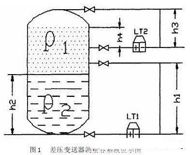
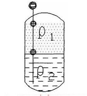
3 example analysis, comparison 3.1 differential pressure transmitter and magnetostrictive level measurement interface analysis and comparison Figure 1,2 is a chemical plant typical chemical reactor level measurement diagram. Above is the oil (benzene and its compounds) The following is a liquid catalyst. Because the density of the catalyst is greater than that of the oil, the two materials are automatically separated. The process operator controls the catalyst, oil interface (LT1 measurement) and oil level (LT2 measurement) to ensure the formation of the synthesis reaction. The two liquid level values ​​must be precisely controlled within a certain range, which is the system parking interlock point.
 (1) Analysis of the cause of interface error using differential pressure transmitter (Figure 1)
In the initial stage, we used a differential pressure transmitter to measure the differential pressure transmitter to determine the zero point and range of the instrument using oil density and catalyst density. These two values ​​were calculated theoretically.
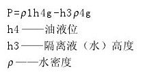
Take Figure 1 as an example to calculate differential pressure (P) for differential pressure transmitter (LT1): The actual oil mixture is separated in the tank. The above oil contains a catalyst, the following catalyst also contains oil, and there are over-thick layers and different density layers at the water-oil interface. The actual density and theoretical values ​​of the two materials are in error; the winter temperature in the northern region is 0 degrees. In the following, the instrument needs to use steam to trace heat. As the steam heating will cause vaporization of the liquid in the pressure guiding tube, the density of the liquid will change after vaporization. Based on the above reasons, it can be seen from the calculation formula that the changes in the density values ​​of Ï1 and Ï2 cause a difference. The pressure level transmitter has a large measurement error, with a maximum error of up to 10.0%. Differential pressure transmitter (LT2) differential pressure (P) formula is:
  The vaporization of the oil in the reactor will cause the liquid in the negative pressure side of the pressure transmitter of the differential pressure transmitter (LT2). Therefore, the negative pressure side of the pressure tube needs to be filled with water. Due to the pressure in the reactor, the pressure guiding tube will enter the oil for a long time on the negative pressure side. With the winter heating, the density of Ï4 will change. The change in Ï4 causes a large measurement error in LT2. To ensure the accuracy of the measurement, flush the pressure tube regularly.
(2) Magnetostrictive Level Gauge (Figure 2)
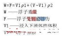
The magnetostrictive level gauge is shipped according to the user's "upper density" and "lower density" to determine the weight of the float. When measuring the interface, the float is actually floating on the interface, and the buoyancy and gravity are equal. The formula is: Because the density of the location of the float is relatively fixed, that is, the percentage of oil and catalyst is relatively fixed. From the above formula, it can be seen that Ï1 and Ï2 are relatively fixed, and the buoyancy of the float is fixed. The float floats accurately on the interface and the liquid surface, thus ensuring high-precision measurement of the magnetostrictive level gauge.
The magnetostrictive liquid level gauge can measure the liquid level and the interface at the same time. In the DCS, the addition and subtraction module uses the liquid level value minus the interface value to obtain the exact height of the oil, and solves the problem that the LT2 in FIG. 1 can only measure the upper part of the oil level. Makes the process operator more aware of the conditions inside the reactor. Differential Pressure Transmitter Pilot Tube Steam heating in winter can cause vaporization of the liquid in the pressure guide tube. It is necessary to perform regular exhaust and filling of the spacer fluid. When the material contains impurities, it will cause the instrument to be blocked. The maintenance personnel of the instrument will have a heavy workload. After the magnetostrictive level gauge, the maintenance of the meter is reduced much.
3.2 Comparison between the interface measurement of a large-scale tank and the level gauge of a servomotor In the measurement of the interface of a large-scale tank in chemical production, the servomotor level gauge and the magnetostrictive level gauge are the most used level gauges. The accuracy is very high. However, the disadvantages of servo motor level gauges are: 1) The mechanical transmission mechanism inevitably brings about the problem of wear; 2) The calibration is complicated; 3) The measurement has a great influence on the fluctuation of the liquid level; 4) The structure is complex and maintenance is difficult. Based on the above reasons, we use a magnetostrictive level gauge that is superior to a servo motor level gauge.
4 Summary Magnetostrictive level gauge as a new measuring instrument has the advantages of high accuracy, stability and reliability. It is more suitable for interface level measurement. In the future, there will be a larger market in the petroleum, chemical, pharmaceutical and other industries.
1.2 Working principle A magnetostrictive line is installed in a non-magnetic sensor tube. A magnetostrictive sensor is installed at one end of the magnetostrictive line. The piezoelectric sensor emits 10 current pulse signals to the magnetostrictive line every second. In time, the current pulse interacts with the magnetic field of the magnetic float to generate a torsional stress wave on the magnetostrictive line that propagates along the magnetostrictive line from both ends of the float at known speeds. Until the piezomagnetic sensor receives this torsional stress signal, the piezomagnetic sensor can measure the time interval between the start pulse and the return torsion stress wave, and judge the position of the float according to the time interval, because the float is always suspended on the liquid surface. The position of the magnetic float changes with the change of the liquid surface, that is, the time interval is the level of the liquid level, and then the full-intelligent electronic device converts the time interval size signal to a 4-20 mA signal proportional to the measured liquid level ( HART) output.
2 Features 2.1 Advantages (1) The structure is simple and consists of only three parts;
(2) High precision, 0.01% of full scale, maximum error no more than 1.27mm;
(3) calibration is extremely simple, no real standard, just press the button or use the HART protocol;
(4) No need to re-calibrate for recalibrating or forgetting the calibration value;
(5) Large measuring range, 0~22m;
(6) Simultaneous measurement of total fluid level and interface fluid level, as well as temperature output;
(7) Large pressure range, maximum 207 Bar, standard is 66 Bar;
(8) Large temperature range, -196°C to 427°C;
(9) Field level transducers such as differential pressure type, capacitive type, ultrasonic type, radar type, outer buoy type, steel belt or servo motor type can be replaced on site.
2.2 Disadvantages (1) High-viscosity liquids and slurries cannot be measured. The antenna is immersed in the liquid to be measured or its saturated vapor. It is not suitable for the measurement of pressurized, self-agglomerating, corrosive, toxic, and highly viscous liquids.
(2) The float moves up and down along the guard tube outside the waveguide and may get stuck.
3 example analysis, comparison 3.1 differential pressure transmitter and magnetostrictive level measurement interface analysis and comparison Figure 1,2 is a chemical plant typical chemical reactor level measurement diagram. Above is the oil (benzene and its compounds) The following is a liquid catalyst. Because the density of the catalyst is greater than that of the oil, the two materials are automatically separated. The process operator controls the catalyst, oil interface (LT1 measurement) and oil level (LT2 measurement) to ensure the formation of the synthesis reaction. The two liquid level values ​​must be precisely controlled within a certain range, which is the system parking interlock point.


In the initial stage, we used a differential pressure transmitter to measure the differential pressure transmitter to determine the zero point and range of the instrument using oil density and catalyst density. These two values ​​were calculated theoretically.
Take Figure 1 as an example to calculate differential pressure (P) for differential pressure transmitter (LT1):


(2) Magnetostrictive Level Gauge (Figure 2)
The magnetostrictive level gauge is shipped according to the user's "upper density" and "lower density" to determine the weight of the float. When measuring the interface, the float is actually floating on the interface, and the buoyancy and gravity are equal. The formula is:

The magnetostrictive liquid level gauge can measure the liquid level and the interface at the same time. In the DCS, the addition and subtraction module uses the liquid level value minus the interface value to obtain the exact height of the oil, and solves the problem that the LT2 in FIG. 1 can only measure the upper part of the oil level. Makes the process operator more aware of the conditions inside the reactor. Differential Pressure Transmitter Pilot Tube Steam heating in winter can cause vaporization of the liquid in the pressure guide tube. It is necessary to perform regular exhaust and filling of the spacer fluid. When the material contains impurities, it will cause the instrument to be blocked. The maintenance personnel of the instrument will have a heavy workload. After the magnetostrictive level gauge, the maintenance of the meter is reduced much.
3.2 Comparison between the interface measurement of a large-scale tank and the level gauge of a servomotor In the measurement of the interface of a large-scale tank in chemical production, the servomotor level gauge and the magnetostrictive level gauge are the most used level gauges. The accuracy is very high. However, the disadvantages of servo motor level gauges are: 1) The mechanical transmission mechanism inevitably brings about the problem of wear; 2) The calibration is complicated; 3) The measurement has a great influence on the fluctuation of the liquid level; 4) The structure is complex and maintenance is difficult. Based on the above reasons, we use a magnetostrictive level gauge that is superior to a servo motor level gauge.
4 Summary Magnetostrictive level gauge as a new measuring instrument has the advantages of high accuracy, stability and reliability. It is more suitable for interface level measurement. In the future, there will be a larger market in the petroleum, chemical, pharmaceutical and other industries.
Sieve Screening,Sieve Screening Machine,Screening Sieve,Sieve Screening Quizlet
RONGCHENG PINGFANG FISHERY MACHINERY CO., LTD. , https://www.pf-fishmealmachine.com